

Flow Rate
up to 900 m³/h
Delivery Head
up to 200 m L.C.
Temperature Range
-40 °C up to +200 °C
Pressure Rating
up to PN 40
key facts
-
Design according to DIN EN ISO 2858 / DIN EN ISO 15783
-
Maintenance-Free Permanent Magnet Drive
-
Modular Design
-
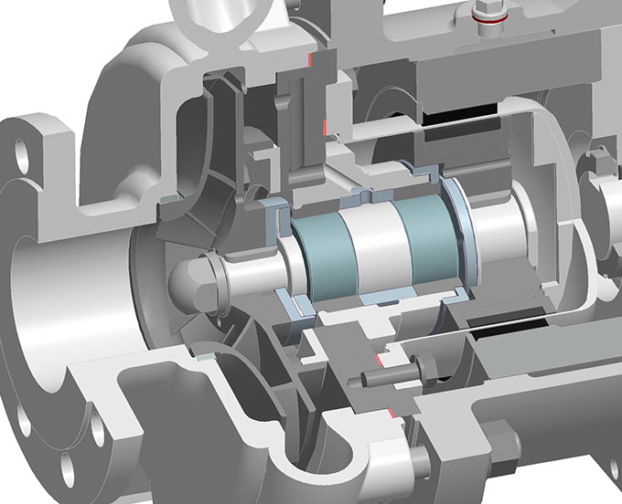
No Dynamic Seal, Separation of Liquid Chamber and Atmosphere by Means of Containment Shell
-
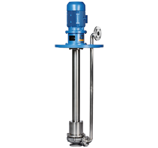
Submerging depth up to 6.000 mm
- Submerged pump with magnet drive
- Submerging depth up to 6.000 mm
- Dry support tube
- Synchronous Permanent Magnet Drive
- Easy to Maintain
- Separation of liquid Chamber and Atmosphere by means of Containment Shell
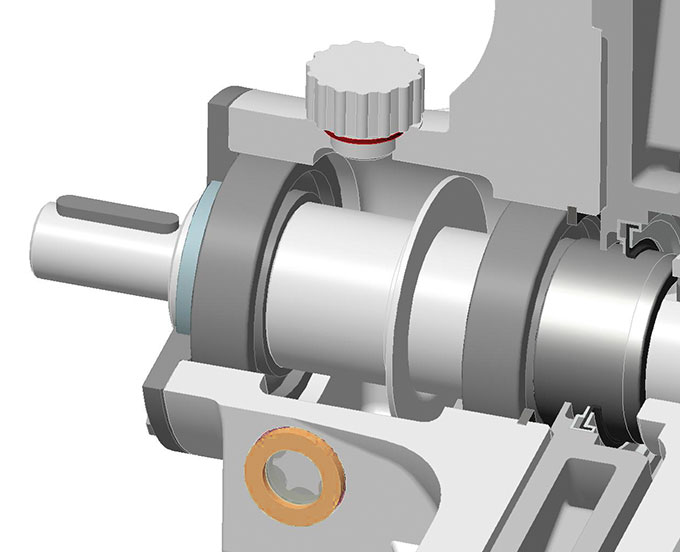
- Greased-for-Life Anti-Friction Bearings
- Product-Lubricated Journal Bearings; Made of Silicon Carbide (SSiC); Customized Materials (e.g. Carbon, WOC etc.) on demand
| Flow Rate | Q | 900 m³/h |
| Delivery Head | H | max. 200 m L.C. |
| Temperature Range | t | -40 °C to +200 °C |
| Pressure Rating | p | max. PN 40 |
Special constructions up to PN100. Higher outputs available.
- Acids
- Lyes
- Hydrocarbons
- Heat Transfer Liquids
- Aggressive, Explosive, Toxic and Malodorous Liquids
- Valuable Liquids
- Industrial Effluent
| Pump casing: | 1.4408 oder 1.0619 |
| Impeller: | 1.4408 |
| Containment shell: | 1.4571/2.4610 |
| Magnet carrier: | 1.4571 |
| Radial journal bearings: | Silicon Carbide |
| Intermediate lantern: | 1.4571 |
| Bearing carrier: | 0.7043 |
| Discharge pipe: | 1.4571 |
| Support tube: | 1.4571 |
Tank flange: 1.4571 or according to customer’s specifications. Other materials available.
NACHSETZZEICHEN (AUSFÜHRUNGEN):
AUSFÜHRUNGSVARIANTEN
The pumps are outfitted with a heat jacket and pump casing (H1) and/or a heat jacket in the bearing lantern (H2). Both heat jackets can be realized either separately or in conjunction with a bypass line. The heat jackets in the standard construction are rated for operating pressure of 16 bar at 200 °C (steam) or 6 bar at 350 °C. The heat jackets can also be used for cooling.
When solids-containing liquids are being transported, the internal filter prevents inadmissibly large particles from entering the flow channels, and from there the magnetic coupling and internal bearings.
These external connections allow for external flushing, feeding and/or venting. Connection E1 is used in situations where a continuous feed into the magnet drive is desired. Connection E2 is used suitable for short-term flushing, or for external venting of the magnetic coupling.
The double isolation shell should be used in situations requiring a high level of safety. The unit consists of two interlocking isolation shells, both of which are rated for the relevant operating conditions. If one of the two units is damaged, the casing still remains leaktight. The gap between the two units can be monitored.