


Flow Rate
up to 200 m³/h
Delivery Head
up to 90 m L.C.
Temperature Range
up to +170 °C
Pressure Rating
up to PN 16
key facts
-
Design according to DIN EN ISO 22858
-
Maintenance-Free Permanent Magnet Drive
-
No Dynamic Seal, Separation of Liquid Chamber and Atmosphere by Means of Containment Shell
-
Liquids only come into contact with the materials PTFE, PFA, zirconium oxide and silicon carbide (SiC)
-
High corrosion resistance
-
The thrust is absorbed by a thrust bearings


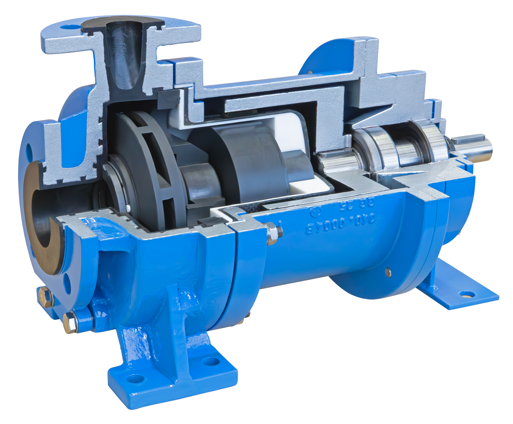
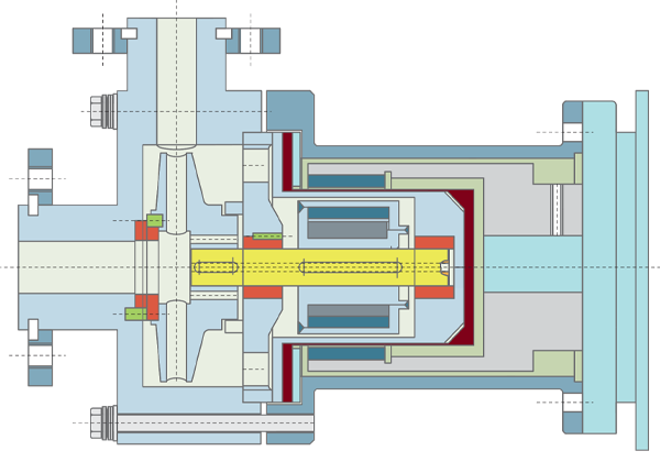
- Single-stage centrifugal pump, process or close-coupled design
- Permanent magnetic drive with PTFE/PFA-lined inner magnet carrier
- Easy to Maintain
- Separation of liquid chamber and atmosphere by means of containment shell
- Vacuum-proof case lining of PFA, 4 mm thick
- Closed PTFE impellers
- Pump shaft, slide and thrust bearings made of high quality silicon carbide
- Optimized power transmission through feather keys
- Special thrust bearings to absorb the shear forces
- Elimination of eddy current losses
| Flow Rate | Q | 200 m³/h |
| Delivery Head | H | up to 90 m L.C. |
| Temperature | t | up to +170 °C |
| Pressure Rating | p | up to PN 16 |
- Acids
- Aggressive, explosive, toxic, hot and malodorous liquids
- Coolants
- Dyes and paints
- Hydrocarbons
- Liquid Gases
- Lyes
- Refrigerants
- Salt Solutions
- Sea Water
- Solvents
- Valuable liquids
- And many more
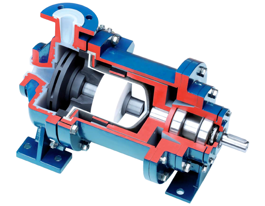
- Pump casing made of GGG-40.3 lined with 4 mm thick PFA
- Impeller: PTFE
- Containment shell: carbon-fibre composite material, lined with PTFE / zirconium oxide
- Inner magnet carrier PTFE-lined
- Journal Bearings: Silicon Carbide
- Bearing Bracket: 0.7043
- Further Materials are available
Flow Rate
up to 200 m³/h
Delivery Head
up to 90 m
Temperature Range
up to +140 °C
Pressure Rating
up to PN 16
key facts
- No Alignment between Pump and Motor
- No Coupling and Coupling Guard
- No Ball Bearings
- Pump does not require scheduled Maintenance
- No lubrication necessary
- Lower noise level
- High Stiffness of the Pump Shaft because of small overhung compared to Pumps with Shaft Seals
- Use of standard high efficient IEC and NEMA Motors contrary to canned Motors
- Better availability with standard Motors
- Maintenance of Motors is standardized and can be done by the customer on site
- Base Plates for Close-Coupled Design do not need to be rigid acc. to API 685 – 7.3


- Close-Coupled Design
- Process Design
- Magnet Drive
- Leak-free
- Horizontal set up
- Modular Design
| Flow Rate | Q= | 3.500 m³/h |
| Delivery Head | H= | up to 220 m |
| Temperature | t= | -120 °C to +450 °C |
| Pressure Rating | p= | up to PN 400 |
- Acids
- Lyes
- Hydrocarbons
- Aggressive, Explosive and Toxic Liquids
- Liquid Gases
- Heat Transfer Liquids
- Coolants
- Liquids Containing Solids
- High-Viscosity Liquids
- Pump casing: 1.4408 or 1.0619
- Impeller: 1.4408
- Containment Shell: 1.4571/2.4610
- Magnet Carrier: 1.4571
- Journal Bearings: Silicon Carbide
- Intermediate Lantern: 1.0619
- Further Materials are available
DESIGN VARIANTS
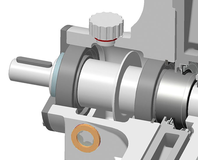
The pumps are outfitted with a heat jacket and pump casing (H1) and/or a heat jacket in the bearing lantern (H2). Both heat jackets can be realized either separately or in conjunction with a bypass line. The heat jackets in the standard construction are rated for operating pressure of 16 bar at 200 °C (steam) or 6 bar at 350 °C. The heat jackets can also be used for cooling.
The thermal barrier acts as a structural element between the bearing carrier (in the bearing carrier model) or drive motor (in the close coupled model), whereas the hydraulic system allows for heat transfer. This reduces ball bearing temperatures in the gearing when hot liquids are being transported. A radial shaft sealing ring can also be integrated into the thermal barrier for purposes of sealing the magnet driver. The sealing ring acts as a secondary seal that prevents the product from leaking into the environment through a leak in the isolation shell. In order for this secondary seal to be used, the magnet driver chamber must be monitored so that leaks can be detected in good time.
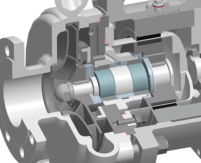
When solids-containing liquids are being transported, the internal filter prevents inadmissibly large particles from entering the flow channels, and from there the magnetic coupling and internal bearings.