

Flow Rate
max. 300 m³/h
Delivery Head
max. 2.200 m L.C.
Temperature Range
-120 °C to +350 °C
Pressure Rating
max. 250 PN
key facts
-
Design according to DIN EN ISO 5199
-
Modular System
-
Shaft Seal Packing; Single or Double Mechanical Seal (also available as a Cartridge Unit)
-
Heating for Casing and Casing Cover available
-
Mechanical Seal-Cover available
-
Design based on API 610 available on Request
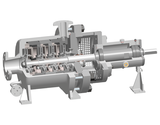


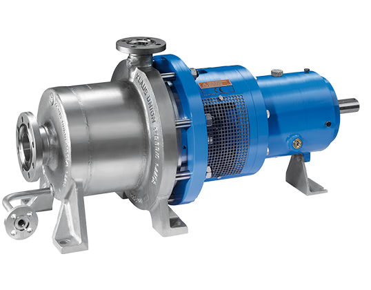
- Multi-Stage Centrifugal Pump in Process Design
- Impeller Arrangement in Series; Max. 6 Stages
- First Low-NPSH Stage for Improved Suction Performance
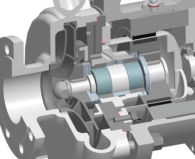
- Shaft Sealing Space for Installation of Mechanical Seals according to DIN EN 12756 or Stuffing Box Packings
- Heating for Casing and Casing Cover available
- Mechanical Seal-Cover available
- Bearing Bracket with Oil-Lubricated Anti Friction Bearings
| Flow Rate | Q | 300 m³/h |
| Delivery Head | H | max. 2.200 m |
| Temperature Range | t | -120 °C to +350 °C |
| Pressure Rating | p | max. PN 250 |
Special configurations available up to PN 400. Higher outputs available.
- Liquid Gases
- Acids
- Lyes
- Hydrocarbons
- Hot Water
- Heat Transfer Liquids
| Pump casing: | 1.4408 or 1.0619 |
| Impeller: | 1.4408 |
| Casing cover: | 1.4571 |
| Shaft: | 1.4462 |
| Shaft Sheath: | 1.4571 |
| Bearing lantern: | 1.0619 |
| Bearing carrier: | 0.7043 |
| Shaft seal: | Acc. to product and/or customer specifications |
Further materials upon request.
| Bearing carrier | Realization | Comments |
| NOV | Standard | Oiled, with deep Groove Ball Bearing |
Flow Rate
max. 540 m³/h
Delivery Head
max. 1.300 m
Temperature Range
-40 °C to + 180 °C
Pressure Rating
max. 100 PN
key facts
-
Design according to DIN EN ISO 5199
-
Modular System
-
Shaft Seal Packing; Single or Double Mechanical Seal (also available as a Cartridge Unit)
-
Heating for Casing and Casing Cover available
-
Mechanical Seal-Cover available
-
Impellers in Pairs or Back-to-Back; max. 6 Stages
-
Design based on API 610 available on Request
- Multi-Stage Centrifugal Pump in Process Design
- Impeller Arrangement in Pairs or back-to-back
- Max. 6 Stages
- First Low-NPSH Stage for Improved Suction Performance
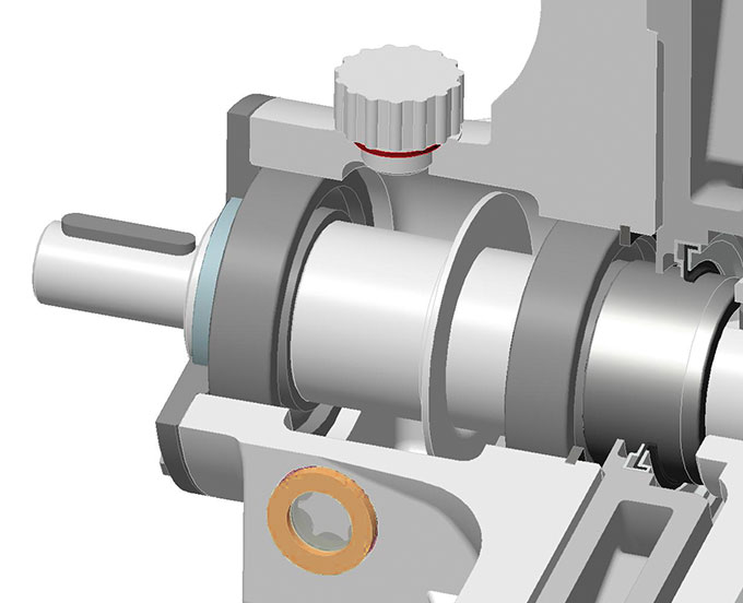
- Shaft Mounted on Roller Bearings Bilaterally Outside the Casing. Alternatively, the Shaft can be Mounted in Fluid-Packed Internal Bearings on the Suction Side
- Shaft Sealed via a Face Seal and Gland Packing
| Flow Rate | Q | 540 m³/h |
| Delivery Head | H | max. 1.300 m |
| Temperature Range | t | -40 °C to +180 °C |
| Pressure Rating | p | max. PN 100 |
Special configurations available up to PN 400. Higher outputs available.
- Liquid Gases
- Acids
- Lyes
- Hydrocarbons
- Hot Water
- Heat Transfer Liquids
| Pump casing: | 1.4408 or 1.0619 |
| Impeller: | 1.4408 |
| Casing cover: | 1.4571 |
| Shaft: | 1.4462 |
| Shaft Sheath: | 1.4571 |
| Bearing lantern: | 1.0619 |
| Bearing carrier: | 0.7043 |
| Shaft seal: | Acc. to product and/or customer specifications |
Further materials upon request.
| Bearing carrier | Realization | Comments |
| NOV | Standard | Oiled, with deep Groove Ball Bearing |
DESIGN VARIANTS
The pumps are outfitted with a heat jacket and pump casing (H1) and/or a heat jacket in the bearing lantern (H2). Both heat jackets can be realized either separately or in conjunction with a bypass line. The heat jackets in the standard construction are rated for operating pressure of 16 bar at 200 °C (steam) or 6 bar at 350 °C. The heat jackets can also be used for cooling.
Inducers are often used in cases where the installation’s NPSH values are extremely low. Inducers substantially reduce pump NPSH throughout the installation without altering pump characteristics. Inducer J can be retrofitted on existing pumps, in most cases with only a minimum amount of pump modification.
NACHSETZZEICHEN (AUSFÜHRUNGEN):
| H1 | heated pump casing |
| H2 | jacketed bearing lantern |
| J | inducer |