

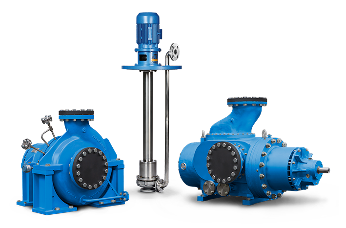
ISO2858
PUMPS ACC. DIN EN ISO 2858
- Max. Flow Rate: 3.500 m3/h
- Max. Delivery Head: 220 m L.C.
- Temperature Range: -200 °C to +450 °C
- Max. Pressure Rating: PN 400
- Ring-Section Design / Barrel Design
- Max. Flow Rate: 1.200 m3/h
- Max. Delivery Head: 215 m L.C.
- Temperature Range: -120 °C to +450 °C
- Max. Pressure Rating: PN 40
- Max. Flow Rate: 3.500 m3/h
- Max. Delivery Head: 220 m L.C.
- Temperature Range: -120 °C to +350 °C
- Max. Pressure Rating: PN 63
- VS4/ VS6 Design
- Max. Flow Rate: 3.500 m3/h
- Max. Delivery Head: 220 m L.C.
- Temperature Range: -40 °C to +200 °C
- Max. Pressure Rating: PN 63
- VS4/ VS6 Design
- Max. Flow Rate: 3.500 m3/h
- Max. Delivery Head: 220 m L.C.
- Temperature Range: -40 °C bis +300 °C
- Max. Pressure Rating: PN 63
API685
PUMPS ACC. API 685
- Max. Flow Rate: 3.500 m3/h
- Max. Delivery Head: 220 m L.C.
- Temperature Range: -200 °C to +450 °C
- Max. Pressure Rating: PN 400
- Ring-Section Design / Barrel Design
- Max. Flow Rate: 300 m3/h
- Max. Delivery Head: 2.200 m L.C.
- Temperature Range: -120 °C to +350 °C
- Max. Pressure Rating: PN 250
- VS4/ VS6 Design
- Max. Flow Rate: 3.500 m3/h
- Max. Delivery Head: 220 m L.C.
- Temperature Range: -40 °C to +200 °C
- Max. Pressure Rating: PN 63
- Max. Flow Rate: 3.500 m3/h
- Max. Delivery Head: 220 m L.C.
- Temperature Range: -120 °C to +350 °C
- Max. Pressure Rating: PN 63
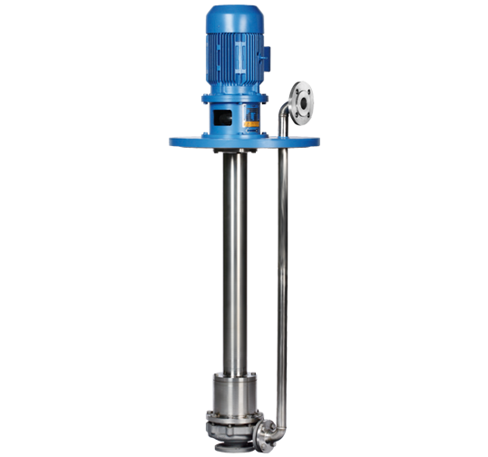
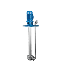
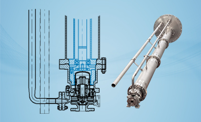
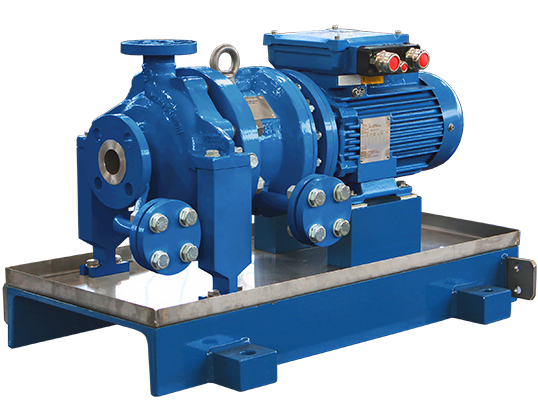
Vertical Inline Pumps
max. 3.500 m³/h max. 220 m L.C. -120 °C to +350 °C PN 40 bei 120 °C KEY FACTS
Special constructions and higher outputs available
Other materials upon request, such as A9, H1, T1Flow Rate
Delivery Head
Temperature Range
Pressure Rating
Design following DIN EN ISO 15783, ASME B73.3M or API 685
Synchronous permanent magnet drive
No dynamic seals, separation of liquid chamber and atmosphere by means of isolation shellf
Secondary Control / Control System by Standard Backup Seal (Optional) acc. API 685


losses / lubrication of journal bearings)Optional:
Flow Rate
Q
3.500 m³/h
Delivery Head
H
up to 220 m L.C.
Temperature Range
t
-120 °C up to +350 °C
Pressure Rating
p
PN 40 at 120 °C
Component
S-8l
A-8
D-1
H2
Pump Casing
Carbon Steel
316 Austenite
Duplex
Hastelloy C4
Impeller
316 Austenite
316 Austenite
Duplex
Hastelloy C4
Wetted Parts
316 Austenite
316 Austenite
Duplex
Hastelloy C4
Shaft
316 Austenite
316 Austenite
Duplex
Hastelloy C4
Intermediate Lantern / Bearing Support
Carbon Steel
Carbon Steel
Carbon Steel
Carbon Steel
Case Studies
CASE STUDIES
PUMPING LIQUID AMMONIA IN A FERTILIZER PRODUCTION COMPLEX
Semi-submerged multi-stage pump with magnetic drive (VS6 Design) / liquid ammonia / fertilizer production
REPLACEMENT OF A MECHANICALLY SEALED HIGH-SPEED PUMP (INTEGRAL GEAR)
Multi-stage centrifugal pump in close-coupled design with magnet drive / crude benzene / transfer
SINGLE-STAGE CENTRIFUGAL PUMP FOR A TRUCK UNLOADING APPLICATION
Dry run capable centrifugal pump in close-coupled design with magnet drive / nitric acid / truck unloading
VERTICAL INLINE PUMP IN A BENZENE DRYING COLUMN
Vertical inline centrifugal pump with magnet drive / benzene / benzene drying column
AVOIDING ANY PRODUCT CONTAMINATION
Twin screw pump with magnet drive / MDI / truck unloading
CENTRIFUGAL PUMP WITH MAGNET DRIVE IN A GAS CONDENSATE APPLICATION
Centrifugal pump with magnet drive / gas condensate / transfer
IMPROVING PUMP AVAILABILITY AND REDUCING OPEX
Twin screw pump with magnet drive / bitumen / circulation, transfer and loading
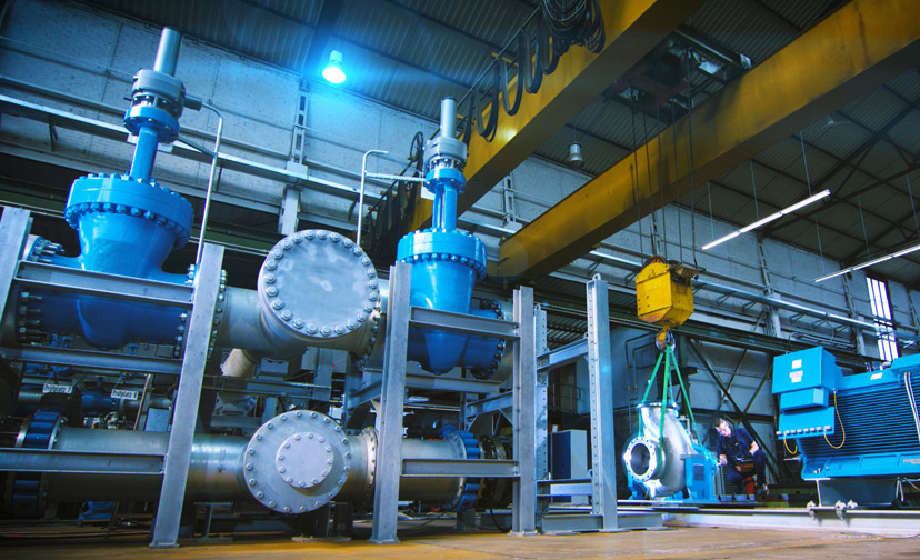
Testing
TESTING
WIDE RANGE
Customers expect the highest quality from our pumps. To ensure this, professional testing of our products to the highest standards is essential. But accurate and reliable testing is also crucial in the course of developing new products.
Klaus Union has various pump test benches that enable a wide range of tests. In this way, customer orders can be tested according to individual requirements.
Test possibilities
- 18 test stations divided into 4 test benches
- Test with water and oil
- Frequency converter operation
- Test runs with low and medium voltage motors
- Performance of string tests
Service performance
- Testing range:
- Q = 0,1 m³/h up to 5.000 m³/h
- H = 2 m L.C. up to 1.000 m L.C.
- ΔP = up to 100 bar
- Motor power: up to 4.5 MW (2.5 MW with frequency inverter)
- n = up to 3.600 min-1
- Mechanical Running Test
- NPSH-measurements
- Axial thrust measurements
- Vibration measurement
- Noise measurement
- Temperature Measurement
MORE TEST POSSIBILITIES
- PMI
- Hydrostatic
- Hardness
- Balancing
- Visual
- Dimensional 3D
- Painting
- Leak: Air, Nitrogen, Helium (external)
- Further tests possible on request
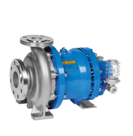
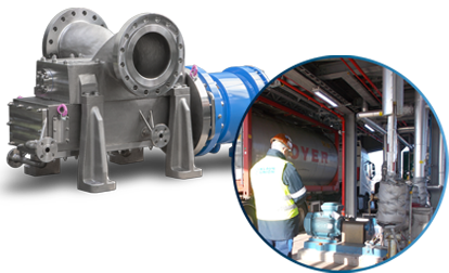
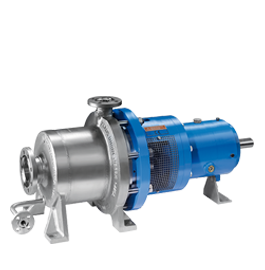
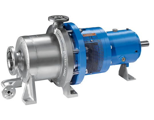
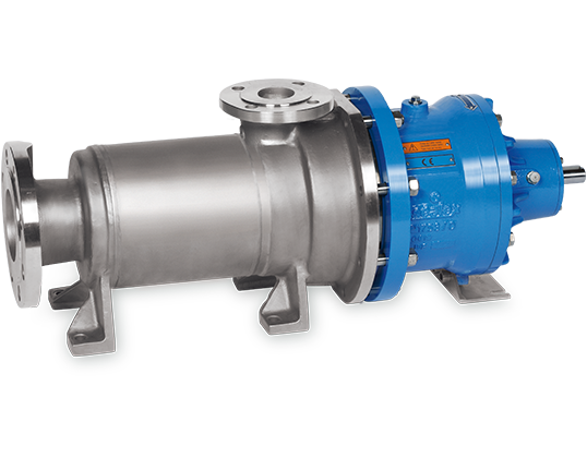
Magnet Drive
KLAUS UNION MAGNET DRIVE
Sealless Technology
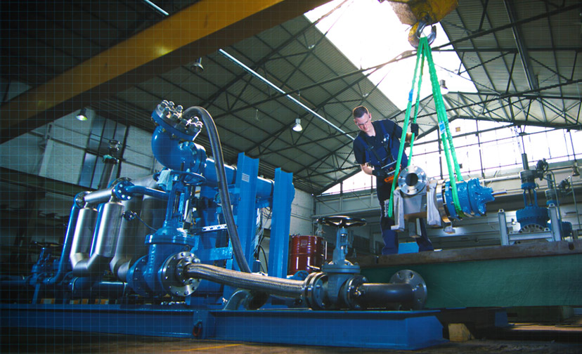
If pumps are used to handle dangerous products, it is essential to avoid even the smallest leakages into the environment in order to ensure the protection of both people and the atmosphere. The ideal solution for such a case is pumps with magnet drive. The first of its kind was introduced by Klaus Union in 1955.
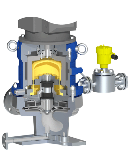
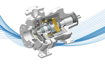
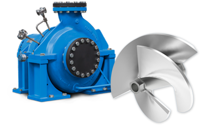
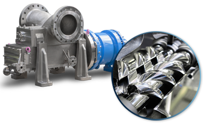
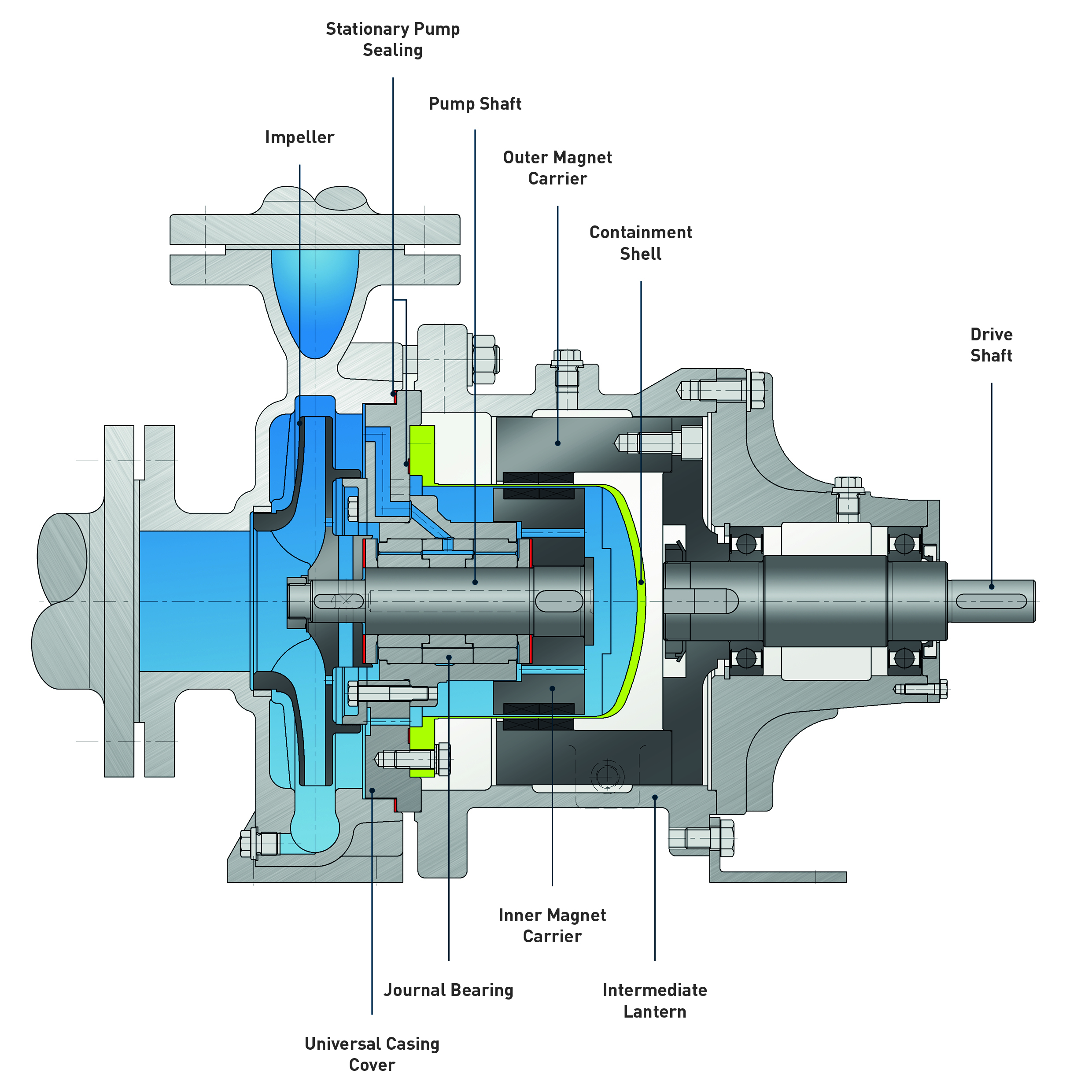
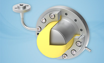
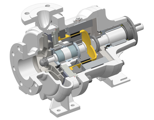
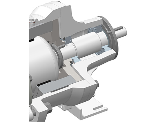
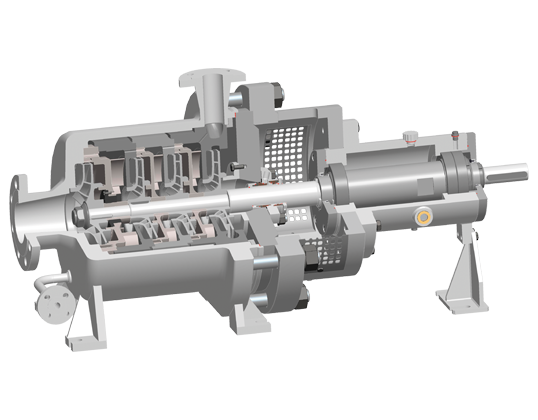
Technical Description
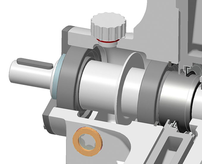
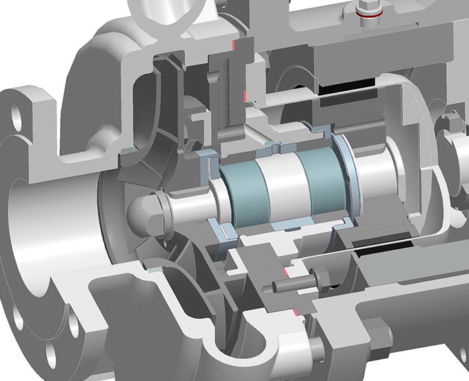
In a magnetic drive pump, the drive shaft – to transfer the mechanical energy from the drive to the pump hydraulics – is not a single shaft with a gland packing or mechanical seal on it. Instead, the energy is transferred contactless from the drive shaft to a pump shaft, using a magnetic coupling. The drive shaft connects the motor with the outer magnet carrier, while the pump shaft holds the inner magnet carrier and the impeller. Both magnet carriers are fitted with permanent magnets, on the inside and the outside respectively. Due to the rotation of the outer magnet carrier, the inner magnet carrier is rotated synchronously via magnetic forces; the mechanical drive energy is transmitted.
Between the magnet carriers, the so-called containment shell is installed to separate the pumped fluid from its environment. The pump shaft is supported by fluid-lubricated maintenance-free slide bearings within the pump’s hydraulic system. There are no dynamic seals between the pumped fluid and the environment from which leakage can escape. Only two static seals are used between pump casing and casing cover and between casing cover and containment shell in the magnetic drive pump.
Advantages vs. Mechanically Sealed Pumps
- Nearly maintenance free
- Less investment costs and less maintenance costs
- No instrumentation or special monitoring devices required in standard
- No utilities required, such as nitrogen or cooling water
- No leakage to the atmosphere
- No loss of sealant liquid
- No wear of the seals at all
- Low mechanical loads on shaft and bearings
- High stiffness of the pump shaft
Advantages vs. Canned Motor Pumps
- Standard IEC and NEMA motors can be used
- Lower investment and repair costs
- Separate flushing of journal bearing
- Higher efficiency
- Use of non- metallic containment shell possible
- No heat generation of the rotor by electric losses
- Higher viscosities possible
- Higher temperatures without cooling possible
- No special monitoring devices necessary
Technical Developments
TECHNICAL DEVELOPMENTS
KLAUS UNION NO VISCO® BEARINGS
Our new NoVisco® bearings can handle extreme solid loads and require no hydrodynamic lubrication film. Thus they do not require any minimum viscosity whatsoever.
This enables Klaus Union pumps to handle applications reliably and without the use of any utilities which were previously impossible to handle reliably with magnetic coupled pumps.

PULLOUT DESIGN FOR VERTICALLY SUSPENDED (SUMP) PUMPS WITH MAGNET DRIVE
Clean and safe maintenance of vertically suspended (sump) pumps with magnet drive
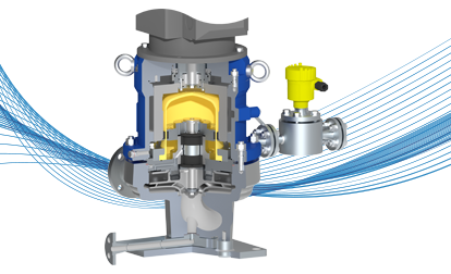
TEMPERATURE MONITORING SYSTEM (TPX)
To further optimize the process reliability of Klaus Union’s magnetically coupled pumps, the TPX temperature monitoring system enables accurate and instantaneous measurement of the containment can temperature.
HYBRID DOUBLE CONTAINMENT SHELL
To reduce the heat generated by a purely metallic, double containment shell and at the same time to improve the overall efficiency of the pump, Klaus Union has developed and patented a new hybrid double containment shell.
Secondary mechanical seal
Secondary mechanical seal as a cost efficient additional layer of safety for magnetic coupled pumps in particularly hazardous applications.
Non-Metallic Containment Shells
Through the use of non-metallic containment shells instead of the traditionally used metallic containment shells, Klaus Union eliminates eddy current losses and increases the efficiency of magnet drive pumps significantly.
Dry Running Design
For the case of a flow interruption, Klaus Union has developed the RTZ Design for magnet drive centrifugal pumps.
Pumps according to this special design conveying water-like media can handle a dry run on suction side for up to 10 minutes. The increase of the containment shell surface temperature is relatively slight.
Handling Liquids Containing Solids
Available design features for magnetically coupled centrifugal pumps to safely handle liquids containing solids.
Greased-for-life Lubrication
Effective from August 1, 2016, Klaus Union offers greased- for-life antifriction bearings (2Z/WT: two sealing discs) for pumps with grease lubricated drive frame as a standard.
The upgrade does not incur a cost adder. It provides various benefits for customers.
GOV/H
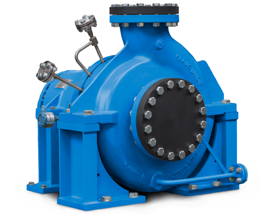
max. 300 m³/h max. 2.200 m L.C. -120 °C to +350 °C max. 250 PN key facts
Special configurations available up to PN 400. Higher outputs available. Further materials upon request. max. 540 m³/h max. 1.300 m -40 °C to + 180 °C max. 100 PN key facts
Special configurations available up to PN 400. Higher outputs available. Further materials upon request. DESIGN VARIANTS The pumps are outfitted with a heat jacket and pump casing (H1) and/or a heat jacket in the bearing lantern (H2). Both heat jackets can be realized either separately or in conjunction with a bypass line. The heat jackets in the standard construction are rated for operating pressure of 16 bar at 200 °C (steam) or 6 bar at 350 °C. The heat jackets can also be used for cooling. Inducers are often used in cases where the installation’s NPSH values are extremely low. Inducers substantially reduce pump NPSH throughout the installation without altering pump characteristics. Inducer J can be retrofitted on existing pumps, in most cases with only a minimum amount of pump modification. NACHSETZZEICHEN (AUSFÜHRUNGEN):Flow Rate
Delivery Head
Temperature Range
Pressure Rating
Design according to DIN EN ISO 5199
Modular System
Shaft Seal Packing; Single or Double Mechanical Seal (also available as a Cartridge Unit)
Heating for Casing and Casing Cover available
Mechanical Seal-Cover available
Design based on API 610 available on Request
Flow Rate
Q
300 m³/h
Delivery Head
H
max. 2.200 m
Temperature Range
t
-120 °C to +350 °C
Pressure Rating
p
max. PN 250
Pump casing:
1.4408 or 1.0619
Impeller:
1.4408
Casing cover:
1.4571
Shaft:
1.4462
Shaft Sheath:
1.4571
Bearing lantern:
1.0619
Bearing carrier:
0.7043
Shaft seal:
Acc. to product and/or customer specifications
Bearing carrier
Realization
Comments
NOV
Standard
Oiled, with deep Groove Ball Bearing
Flow Rate
Delivery Head
Temperature Range
Pressure Rating
Design according to DIN EN ISO 5199
Modular System
Shaft Seal Packing; Single or Double Mechanical Seal (also available as a Cartridge Unit)
Heating for Casing and Casing Cover available
Mechanical Seal-Cover available
Impellers in Pairs or Back-to-Back; max. 6 Stages
Design based on API 610 available on Request
Flow Rate
Q
540 m³/h
Delivery Head
H
max. 1.300 m
Temperature Range
t
-40 °C to +180 °C
Pressure Rating
p
max. PN 100
Pump casing:
1.4408 or 1.0619
Impeller:
1.4408
Casing cover:
1.4571
Shaft:
1.4462
Shaft Sheath:
1.4571
Bearing lantern:
1.0619
Bearing carrier:
0.7043
Shaft seal:
Acc. to product and/or customer specifications
Bearing carrier
Realization
Comments
NOV
Standard
Oiled, with deep Groove Ball Bearing
H1
heated pump casing
H2
jacketed bearing lantern
J
inducer
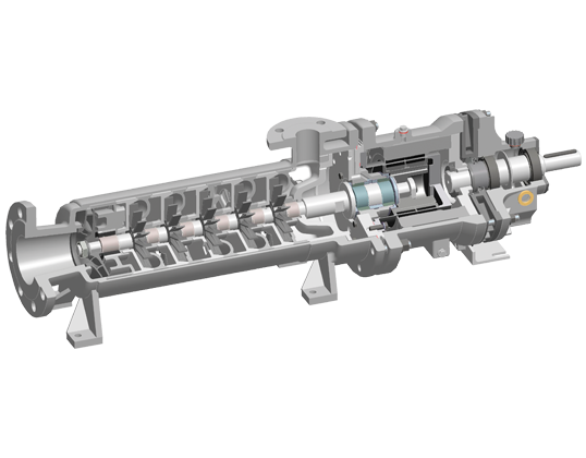
SLM SV
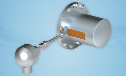
max. 42 m³/h max. 470 m L.C. -120 °C to +250 °C max. PN 400 KEY FACTS
Higher flow rates upon request. Further materials upon request. max. 42 m³/h max. 470 m -120 °C to +300 °C max. PN 400 key facts
Higher flow rates upon request
NACHSETZZEICHEN (AUSFÜHRUNGEN): DESIGN VARIANTS The pumps are outfitted with a heat jacket and pump casing (H5) and/or a heat jacket in the bearing lantern (H2). Both heat jackets can be realized either separately or in conjunction with a bypass line. The heat jackets in the standard construction are rated for operating pressure of 16 bar at 200 °C (steam) or 6 bar at 350 °C. The heat jackets can also be used for cooling. The thermal barrier acts as a structural element between the bearing carrier (in the bearing carrier model) or drive motor (in the close coupled model), whereas the hydraulic system allows for heat transfer. This reduces ball bearing temperatures in the gearing when hot liquids are being transported. A radial shaft sealing ring can also be integrated into the thermal barrier for purposes of sealing the magnet driver. The sealing ring acts as a secondary seal that prevents the product from leaking into the environment through a leak in the isolation shell. In order for this secondary seal to be used, the magnet driver chamber must be monitored so that leaks can be detected in good time. The double isolation shell should be used in situations requiring a high level of safety. The unit consists of two interlocking isolation shells, both of which are rated for the relevant operating conditions. If one of the two units is damaged, the casing still remains leaktight. The gap between the two units can be monitored. Flow Rate
Delivery Head
Temperature Range
Pressure Rating
Design following DIN EN ISO 15783
Maintenance-Free Permanent Magnet Drive
Modular Design
No Dynamic Seal, Separation of Liquid Chamber and Atmosphere by Means of Containment Shell
Barrel Design Version with only two static Seals
Impeller Arrangement in Series; max. 8 Stages
Self-Priming; First Low-NPSH Stage for Improved Suction Performance
FLOW RATE
Q
42 m³/h
DELIVERY HEAD
H
max. 470 m L.C.
TEMPERATURE
t
-120 °C to +250 °C
PRESSURE RATING
p
max. PN 400
Casing elements:
315 SS
Impeller/Paddle wheels:
316 SS
Containment shell:
316 Ti/Hastelloy C4
Magnet carrier:
316 Ti
Radial journal bearings:
Silicon Carbide
Intermediate lantern:
Nodular Iron
Bearing carrier:
Ductile Iron
Flow Rate
Delivery Head
Temperature Range
Pressure Rating
Flow Rate
Q=
42 m³/h
Delivery Head
H=
max. 470 m
Temperature Range
t=
-120 °C bis +300 °C
Pressure Rating
p=
max. PN 400
Gehäuseteile:
1.4408
Laufrad/Flügelräder:
1.4408
Spalttopf:
1.4571/2.4610
Magnetträger:
1.4571
Gleitlagerung:
Siliciumcarbid
Zwischenlaterne:
1.0619
H1
heated pump casing
H2
jacketed bearing lantern
S
thermal barrier without secondary seal
W
thermal barrier with secondary seal
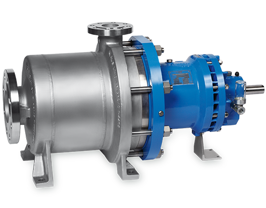
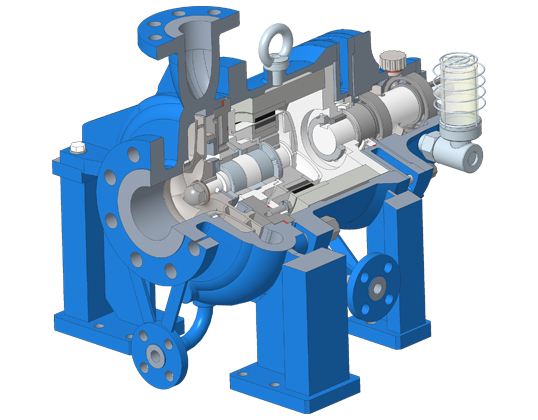
SLM AP
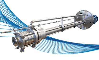
max. 3.500 m³/h max. 220 m L.C. -120 °C to +550 °C max. PN 400 KEY FACTS
Special constructions and higher outputs are available Further materials such as the following are available: H-2 (Hastelloy C), A-9 (Alloy-20), T-1 (Titanium), D-1 (Duplex). max. 3.500 m³/h max. 220 m -120 °C to +350 °C max. PN 400 key facts
Special constructions and higher outputs are available Further materials such as the following are available: H-2 (Hastelloy C), A-9 (alloy-20), T-1 (titanium), D-1 (duplex). NACHSETZZEICHEN (AUSFÜHRUNGEN): DESIGN VARIANTS The pumps are outfitted with a heat jacket and pump casing (H1) and/or a heat jacket in the bearing lantern (H2). Both heat jackets can be realized either separately or in conjunction with a bypass line. The heat jackets in the standard construction are rated for operating pressure of 16 bar at 200 °C (steam) or 6 bar at 350 °C. The heat jackets can also be used for cooling. When solids-containing liquids are being transported, the internal filter prevents inadmissibly large particles from entering the flow channels, and from there the magnetic coupling and internal bearings. These external connections allow for external flushing, feeding and/or venting. Connection E1 is used in situations where a continuous feed into the magnet drive is desired. Connection E2 is used suitable for short-term flushing, or for external venting of the magnetic coupling. The double isolation shell should be used in situations requiring a high level of safety. The unit consists of two interlocking isolation shells, both of which are rated for the relevant operating conditions. If one of the two units is damaged, the casing still remains leaktight. The gap between the two units can be monitored. Inducers are often used in cases where the installation’s NPSH values are extremely low. Inducers substantially reduce pump NPSH throughout the installation without altering pump characteristics. Inducer J can be retrofitted on existing pumps, in most cases with only a minimum amount of pump modification.Flow Rate
Delivery Head
Temperature Range
Pressure Rating
Design according to API 685
Maintenance-Free Permanent Magnet Drive
Modular Design
No Dynamic Seal, Separation of Liquid Chamber and Atmosphere by Means of Containment Shell
Flow Rate
Q
3.500 m³/h
Delivery Head
H
max. 220 m L.C.
Temperature Range
t
-200 °C to +550 °C
Pressure Rating
p
max. PN 400
Component
A-8
S-8
Pump casing
316 austenite
Cast steel
Impeller
316 austenite
316 austenite
Containment shell
Hastelloy C
Hastelloy C
Pump shaft
316 austenite
316 austenite / C-steel
Intermediate lantern / Bearing carrier
Cast steel
Cast steel
Drive shaft
C-steel
C-steel
Flow Rate
Delivery Head
Temperature Range
Pressure Rating
Flow Rate
Q=
3.500 m³/h
Delivery Head
H=
max. 220 m
Temperature Range
t=
-120 °C to +350 °C
Pressure Rating
p=
max. PN 400
Component
A-8
S-8
Pump casing
316 austenite
Cast steel
Impeller
316 austenite
316 austenite
Containment Shell
Hastelloy C
Hastelloy C
Pump shaft
316 austenite
316 austenite / C-steel
Bearing lantern/bearing carrier
Cast steel
Cast steel
Drive shaft
C-steel
C-steel
H1
beheiztes Pumpengehäuse
H2
beheizte Zwischenlaterne
F
Innenfilter
E1
externe Einspeisung, interne Teilstrombohrungen verschlossen
E2
externe Spülung / Entlüftung, interne Teilstrombohrungen offen
E1F
externer Teilstrom mit Hauptstromfilter nach DGRL
D
Doppelschaliger Spalttopf
J
Inducer